I. INTRODUCTION
As the human population continues to expand, humans increasingly encounter birds and animals rarely encountered in the past. Exposure to and infection by special pathogens originating from rare birds and animals is a growing social problem. Implanting microcapsules into birds or animals capable of electrically detecting antigen-antibody reactions would make it possible to monitor avian influenza outbreaks (including outbreaks of strains that are merely weakly pathogenic) and other zoonotic diseases, such as West Nile fever and scrub typhus. In essence, this would establish an early warning system that issues geographical alerts for emerging diseases, making it possible to respond or even to prevent the emergence of such disease. In the case of migratory birds, implanting such a device in one bird per 100 may be sufficient to monitor an entire flock. Beyond this, some 80 billion poultry birds are grown commercially around the world. A system that implants a 10-yen antigen-antibody reaction sensor in each young bird potentially opens the doors to a vast market on the scale of 800 billion yen.
The power supply in the body came using RF power from the outside the body until now. According to the report of Chaimanonart[2], a miniature, long-term, implantable radio frequency power converter for freely moving small animal in vivo biological monitoring was tested. His environment consisting of a laboratory mouse inside a cage is used and by employing an inductive coupling network, a prototype implant device that was consisted with switching frequency 250-320kHz and two piece of Ferrocube 3F3 and 17-19 turns of AWG38 wires. It seems heavy duty application to support artificial heart. So this power supply is inefficient, and the machine parts (device providing RF) to install outside a body become large-scale. Therefore we groped for another solution.
Conventional subcutaneous sensors are not exposed to sunlight and require an external energy source, such as microwaves. Our goal is to develop a small power-generating device that harnesses the kinetic energy of walking, flapping, and other movements to generate electric potential through electromagnetic induction. This article provides a brief overview of such a device.
II. PRINCIPLE AND HARDWARE
Faraday’s law of electromagnetic induction magnetic field lines indicate the direction of the magnetic field strength H; magnetic flux lines indicate the direction of the magnetic flux density B; and the total number of magnetic flux lines is the magnetic flux.
When a magnetic field of magnetic flux density B perpendicularly passes through a closed circuit of area S, the magnetic flux Φ passing through the area is expressed by the following equation:
If Φ is constant, nothing happens. If Φ changes, the electromotive force induced generates a current along the closed circuit in the direction opposite the original change in the magnetic flux. This is known as Lenz’s law.
Let us denote the induced electromotive force along the closed circuit as V and define the positive direction of V as the direction of the current generating the original magnetic flux Φ. Then, V is given by the following equation:
The case of N number of turns of the coil is expressed as follows:
Equations (1) and (2) are known as Faraday’s law of electromagnetic induction. Here, the negative sign may be replaced by the positive sign, depending on how the positive direction of the electromotive force V is defined. We will assume a negative sign unless otherwise stated in the problem.
For example, consider a coil whose diameter is 7 mm (with cross section of 0.00385 m2) and whose number of turns is 6,100. Assume that the magnetic flux density passing upward through the coil increases at the rate of 0.40 T (teslas) per second.
According to Lenz’s law, we can calculate the induced electromotive force that generates a current to oppose this increase. Since the magnetic flux increases at 0.40 × 0.00385 = 0.00154 Wb (webers) per second, the electric potential V generated at the terminal is expressed as follows:
If the magnet moves vertically according to a sine curve with respect to time, we obtain an alternating current with effective power of 9.39 V.
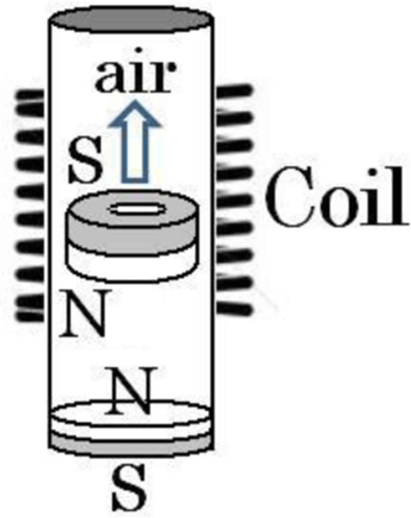
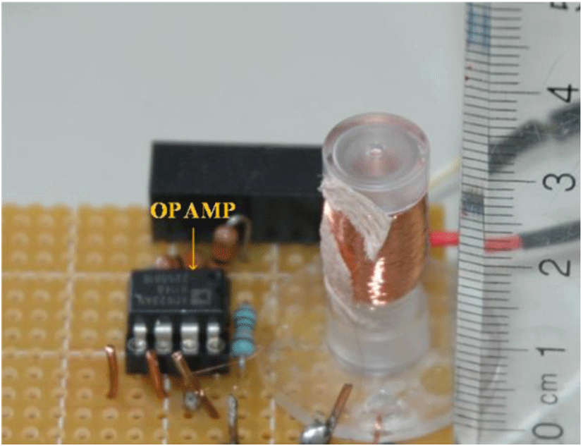
The coil prepared for evaluation has the following specifications. A copper wire measuring 0.03 mm in diameter is smoothly wound 6,100 turns (center-tapped at 3,050 turns) around a bobbin with a hand-operated coil winding device (total weight 4g). The magnet inserted is made of neodymium magnets (specification given in Table 1). Four magnets are serially connected along the axis to form an 8-mm long cylindrical magnet. The electric potential generated by the oscillations is amplified with an operational amplifier with an amplification factor of 2 and recorded with a small data logger (24 g).
III. EXPERIMENTS
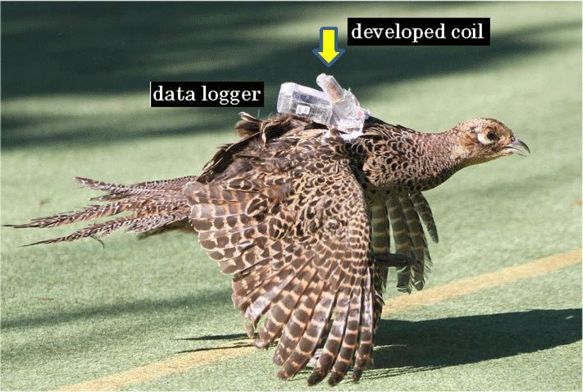
We attached the developed coil to chickens and pheasants and recorded the electric potential generated as the pheasant flew in a huge cage.
Since evaluation of the coil (Figure 1, Figure 2) performed by experiments only with birds was not completed, we have developed the physical simulator (Figure 5) and evaluated the voltage output. The measurement circuit was shown in Figures 3 and 4. The summarized the specification of the magnet which vibrates inside a bobbin (6 mm in inside diameter, 7 mm of outer diameters) is shown in Table 1. In order to avoid the magnetic interfere from the drive system (AC100V motor), we extended the vibration with 1 m in length a nonmagnetic material, and put the plate on the extended stick, and measured voltage in the state angle 90 degrees. Figure 6 is the flapping-of-wings vibration 480/min (8 Hz). The value calculated with the Fast Fourier Transform of the generating voltage at the time of R= 2200 ohms of load resistance is Figure 7. Although given vibration is 8 Hz, the Tast Fourier Transform (FFT) peak is in 26 Hz, as with parasitism vibration inside of bobbin. Given vibration, and the p-p voltage and average voltage (integration value) which were squeezed out were shown in Fig. 8.


The flight experiments (outdoor) were performed with Japanese pheasants carrying small data recorder or hi-vision camera on their back. We have tested total 13 Japanese Pheasants( female).

IV. CONSIDARATIONS
The electric potential generated by walking or flapping is equal to or exceeds the 10 V peak-to-peak at maximum. Even if we account for the junction voltage of the diode (300 mV), efficient charging of the double-layer capacitor is possible with the voltage doubler rectifier. If we increase the voltage, other problems arise, including the high-voltage insulation of the double-layer capacitor. For this reason, we believe the power generated to be sufficient.
The coil developed for evaluation in this study is relatively large for implantation, although it can still be implanted in an adult chicken or other bird of similar dimensions. Further reductions in size will allow use with medium-sized migratory birds such as gulls.
Although the average current obtained with the evaluation coil is approximately 0.1 mA, electric potential is continuously generated throughout the day. Thus, we estimate one antigen-antibody reaction test could be performed roughly once per week. Of course, transmitting data to an external device will require a communication device fitted to the back of the bird or animal. Because we developed a physical simulator such as Figure 6, we intent to analyze the correlation of generation voltage and flap.
Electric potential does not increase to 180/minute(flapping). Because this has lighter weight of the magnet than angular acceleration. From 200 to 560/minute it looks linearly, and it may be said that this frequency is the most suitable use of this coil[Fig.8]. More than 560/minute, the increase of electric potential becomes slow. Because a magnet hits a ceiling, electric potential is saturated. In future, creating miniature of the coil for small birds, we have to perform the optimization of the from maximum quantity of electricity.
Based on the Fig.6 currently surveyed by vibration, the peak of the power spectrum (Figure 7) has appeared in 26 Hz by flapping of wings of 8Hz by load resistance (2200ohm+2200ohm total=4.4k) simulated flapping at 480 times. The peak voltage at this time (average) looks 2.623 [V], and since that 1/2 lambda can read it with about 10 msec(s), if the magnetic flux density generated by one wave from this is calculated, it will be set to 111.73[mT] =1117.3 [a gauss] (coil of 15 mm length) at a peak. It can be guessed that averages are the numerical value broken by the route 2 that makes 78.9 [mT]. Regarding the efficiency, magnetic 2 mm in length and coil 15mm in length, if axial direction is rectified, the magnetic flux density given to the coil could calculated to 7.1 %, and generated power 0.47mW/sec.. Since the efficiency of the motor which rotates centering on an axis will be not less than 80%, we think it is this low value 7.1[%]. If copper wire around 7 mm (6 mm in inside diameter of a bobbin) length of 15 mm 6100 times, it will be calculated the inductance to 75.1mH. However, actual measurements are 43.5mH and the efficiency will be 58%. This does not have the perfect insulation of 0.03-mm copper wire that makes the leak current. If the leak current of 42% (100-58%) covered with epoch-making insulating varnish, the real efficiency of 7.1% will be improved tremendously. The improvement of insulation is expected in the future.
V. CONCLUSION
We developed the small coil which supplies an electronic power to the device for wild birds, especially embed at a subcutaneous part in the future. We checked it with physical simulation estimating performance, and generating electricity by flapping of wings of pheasant. We intend to put into a glass capsule and to embed at a subcutaneous part or the abdominal cavity in the future to detect the reaction of antigen and antibody of avian influenza.


